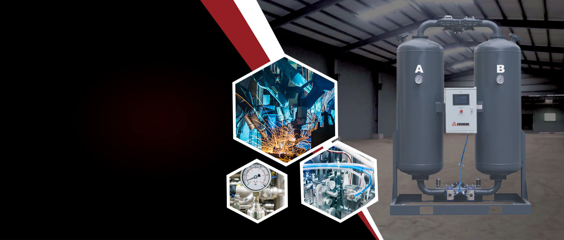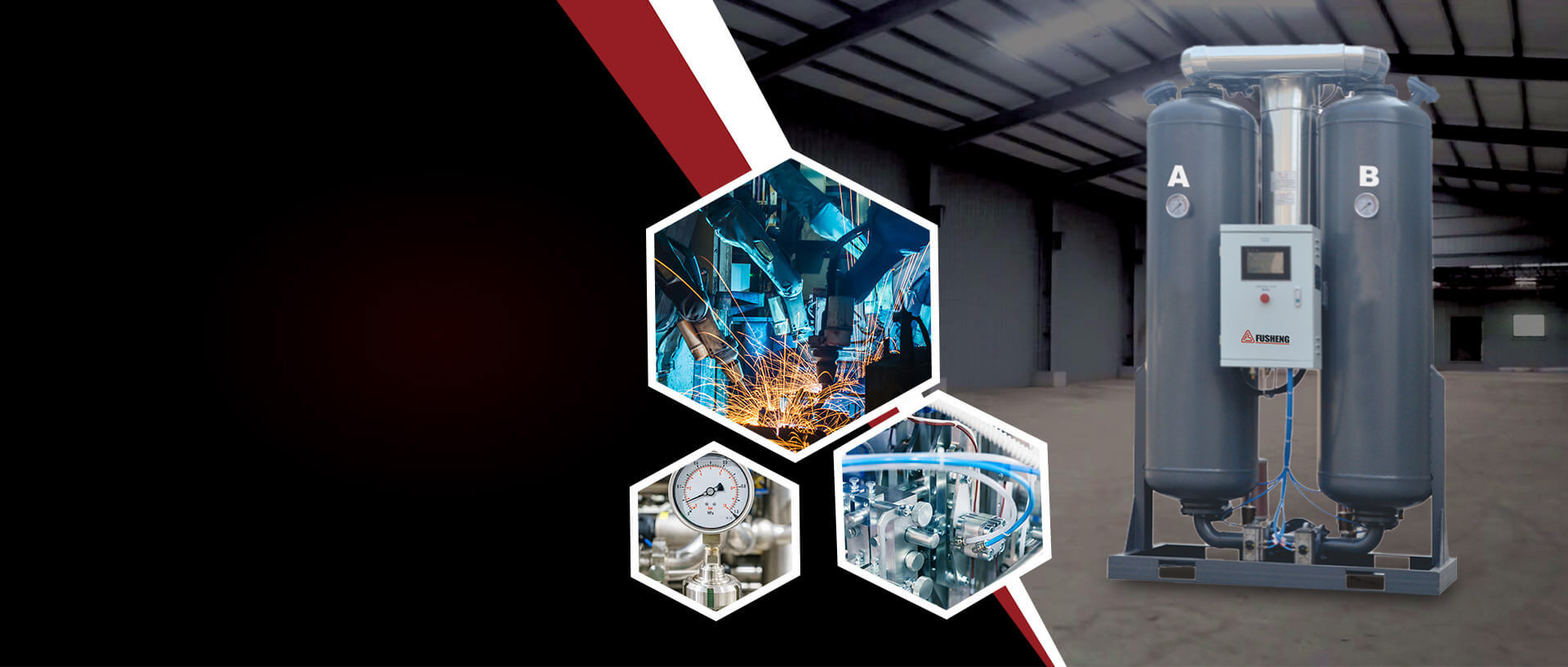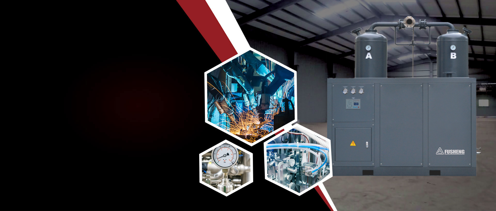
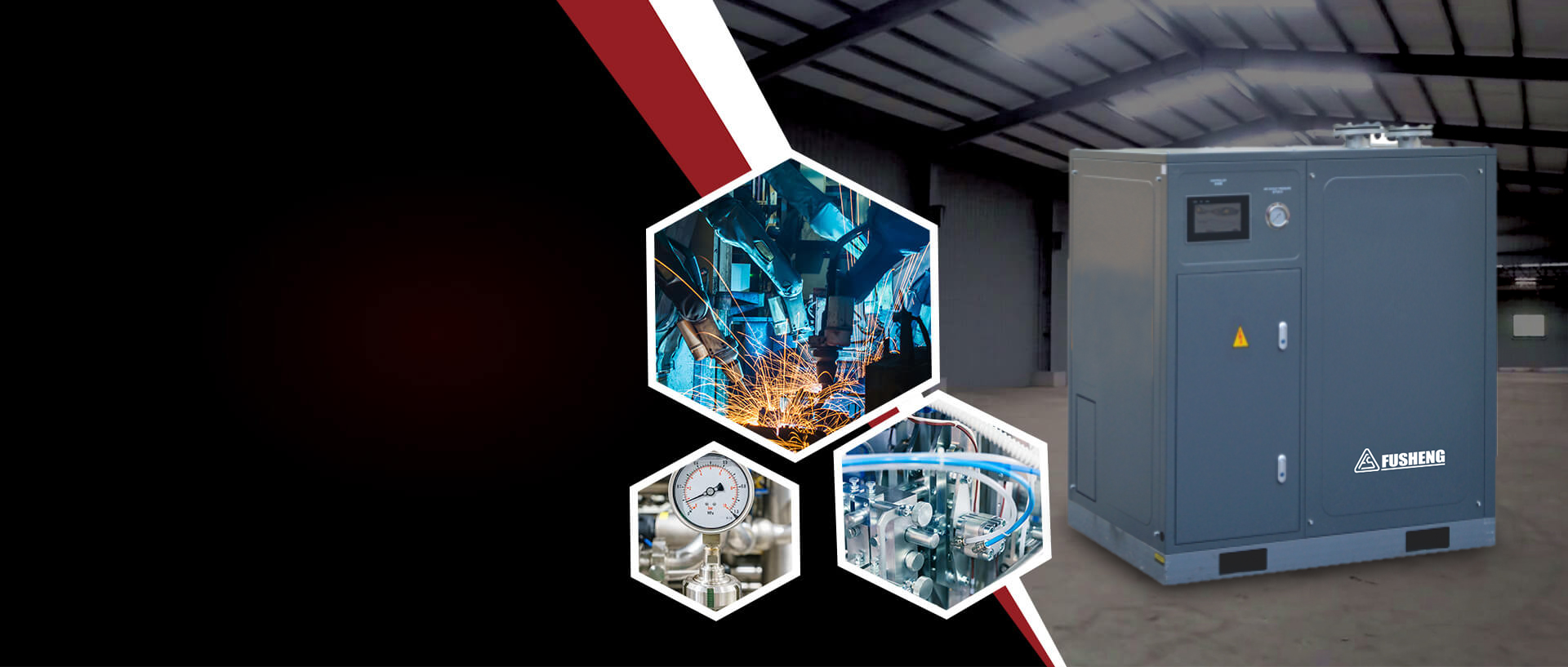
Compressed air leaving an air compressor usually carries a lot of moisture. If that water is not removed before the air enters the network, it accumulates in the pipes, condenses at low points and eventually reaches the point of use as liquid water. Frozen and blocked lines in winter, corroded pneumatic components, water marks in spray finishes, inaccurate instrument readings — many inexplicable failures trace back to excessive moisture in the air supply. Fitting a dryer between the compressor and the point of use is therefore standard practice in almost every compressed air system.
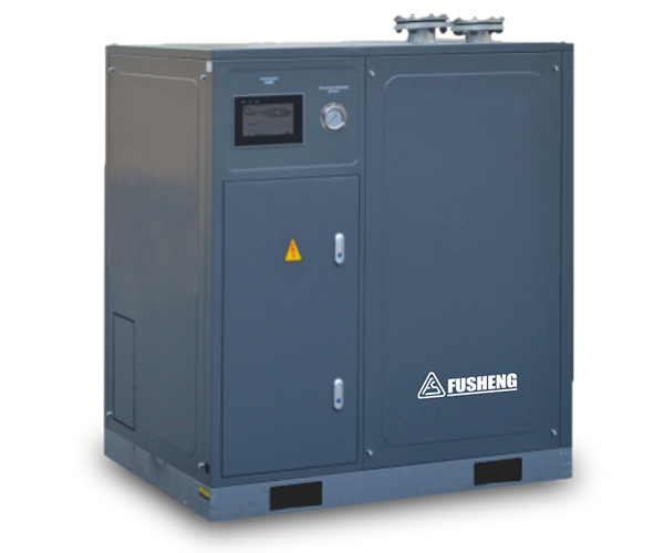
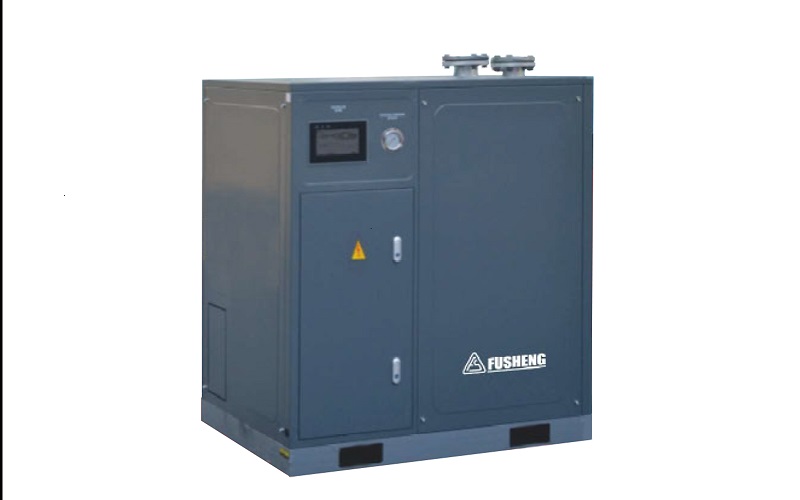
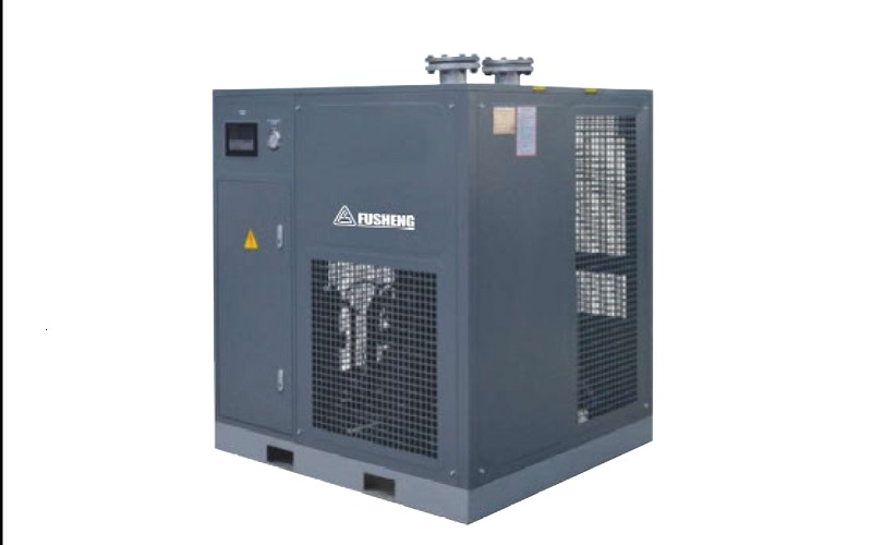
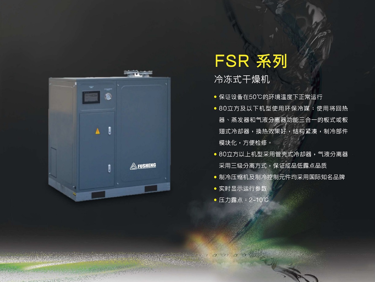
The Fusheng FSR refrigerated dryer covers 8.5-90 m³/min and comes in water-cooled, high-temperature air-cooled and low-temperature air-cooled versions, making it a mainstay of compressed air treatment.
Air itself contains water vapour, in an amount that depends on ambient temperature and humidity. When air is compressed its volume shrinks, so the concentration of water vapour per unit volume rises several times over; and the compression process also raises the temperature, so the air appears able to hold more moisture. Once the compressed air cools in the network, the upper limit on moisture content falls and the excess condenses into liquid water. In other words, dewatering is essentially cooling the compressed air to a target dew point and then separating out the water that condenses.
A refrigerated dryer works around cooling: it cools the compressed air to a set temperature so the water vapour condenses into liquid water, then discharges the water through a separator to obtain dry air with a lower dew point. It is relatively simple in structure, stable in operation, and its energy consumption is mainly that of the refrigerant compressor, making it the most widely used type of dryer. For most routine industrial air applications the dew point it provides is sufficient and its running cost is relatively controllable. Note that this dew point has limits and cannot serve processes with more demanding air requirements, so in practice dryers are often used together with filters and air receivers to form a complete air treatment chain, each doing its own job.
Because drying is only one link in the air treatment chain, it should not be treated as a standalone device during selection: inlet conditions, capacity, target dew point and the requirements of downstream equipment are all parameters on the same drawing and must be calculated together.
The FSR series is divided into several branches by cooling method and inlet conditions, and selection must match site conditions:
Water-cooled versions use circulating cooling water to carry away heat; cooling efficiency is high and ambient temperature has little effect, suiting larger capacities where a stable supply of circulating water is available.
Air-cooled versions use air cooling, need no cooling water system and are more flexible to install, suiting locations where water is inconvenient or running water pipes is impractical.
High-temperature versions are made for duties with a high inlet temperature. When compressor discharge enters the dryer directly without pre-cooling, the inlet temperature is clearly above normal; a standard model cannot cope, and only a high-temperature model ensures consistent dewatering. Always confirm the inlet temperature first during selection — this is the easiest step to get wrong.
| Item | Specification |
|---|---|
| Model | FSR Series refrigerated dryer |
| Capacity | 8.5 - 90 m³/min |
| Cooling method | Water-cooled / air-cooled |
| Variants | Water-cooled / high-temperature air-cooled / low-temperature air-cooled |
| Representative models (water-cooled) | FSR-60W to FSR-150W |
| Representative models (high-temperature air-cooled) | FSR-10AP to FSR-50AP |
| Representative models (low-temperature air-cooled) | FSR-10A to FSR-50A |
| Inlet/outlet size | G1 - DN65 |
| Power supply | 220V / single phase (by model) |
The table shows the FSR coverage logic: water-cooled models win on capacity and suit high-flow central supply, while air-cooled models excel in installation flexibility and suit small-to-medium flow and distributed layouts. Inlet/outlet sizes step up from G1 to DN65 across the branches, and selection should match the connection to the existing pipe size.
A refrigerated dryer is not the most expensive device in the system, but it is the key link that decides how dry the air supply is. Removing water before it enters the network is far more economical than tracking it down later through equipment failures. With 8.5-90 m³/min of capacity and multiple branches, the FSR series offers a systematic set of choices for different duties.
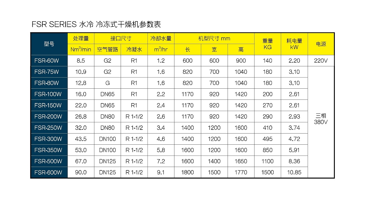
| Model | Capacity | Nm°/min | Air Piping | Connection Size | Condensate | Cooling Water Flow | m"/hr | Dimensions mm | Weight | KG | Power Consumption | kw | Power Supply |
|---|---|---|---|---|---|---|---|---|---|---|---|---|---|
| FSR-60W | 8.5 | G2 | R1 | 1.2 | 600 | 600 | 900 | 140 | 2.20 | 220V | |||
| FSR-75W | 10.9 | G2 | R1 | 1.6 | 820 | 700 | 1040 | 180 | 3.10 | ||||
| FSR-80W | 12.8 | R1 | 1.6 | 820 | 700 | 1040 | 180 | 3.10 | |||||
| FSR-100W | 16.0 | DN65 | R1 | 2.2 | 1170 | 920 | 1420 | 200 | 2.61 | ||||
| FSR-150W | 22.0 | DN65 | R1 | 2.4 | 1170 | 920 | 1420 | 270 | 2.61 | ||||
| FSR-200W | 26.8 | DN80 | R 1-1/2 | 2.6 | 1170 | 920 | 1420 | 290 | 2.93 | Three Phase | |||
| FSR-250W | 32.0 | DN80 | R 1-1/2 | 3.4 | 1400 | 1200 | 1600 | 410 | 3.74 | ||||
| FSR-300W | 43.5 | DN100 | R 1-1/2 | 4.6 | 1400 | 1200 | 1600 | 495 | 4.72 | ||||
| FSR-350W | 53.0 | DN100 | R 1-1/2 | 5.8 | 1600 | 1200 | 1600 | 850 | 5.91 | ||||
| FSR-500W | 67.0 | DN125 | R 1-1/2 | 7.2 | 1600 | 1400 | 1650 | 1100 | 8.36 | ||||
| FSR-600W | 90.0 | DN125 | R 1-1/2 | 9.1 | 1800 | 1500 | 1770 | 1500 | 10.85 |
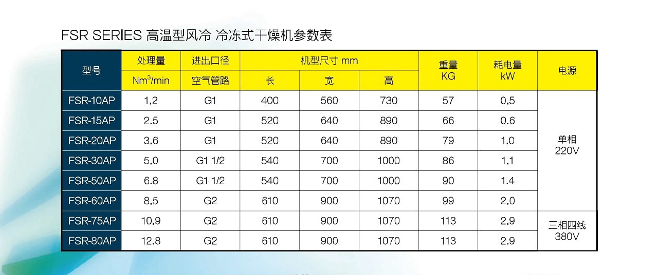
| Model | Nm²/min | Capacity | Inlet/Outlet Size | Air Piping | Dimensions mm | Weight | KG | Power Consumption | kw | Power Supply |
|---|---|---|---|---|---|---|---|---|---|---|
| FSR-10AP | 1.2 | G1 | 400 | 560 | 730 | 57 | 0.5 | |||
| FSR-15AP | G1 | 520 | 640 | 890 | 66 | 0.6 | ||||
| FSR-20AP | 3.6 | G1 | 520 | 640 | 890 | 79 | 1.0 | Single Phase | ||
| FSR-30AP | 5.0 | G1 1/2 | 540 | 700 | 1000 | 86 | 1.1 | |||
| FSR-50AP | 6.8 | G1 1/2 | 540 | 700 | 1000 | 90 | 1.4 | |||
| FSR-60AP | 8.5 | G2 | 610 | 900 | 1070 | 99 | 2.0 | |||
| FSR-75AP | 10.9 | G2 | 610 | 900 | 1070 | 113 | Three Phase, Four Wire | |||
| FSR-80AP | 12.8 | G2 | 610 | 900 | 1070 | 113 | 2.9 | 380V |
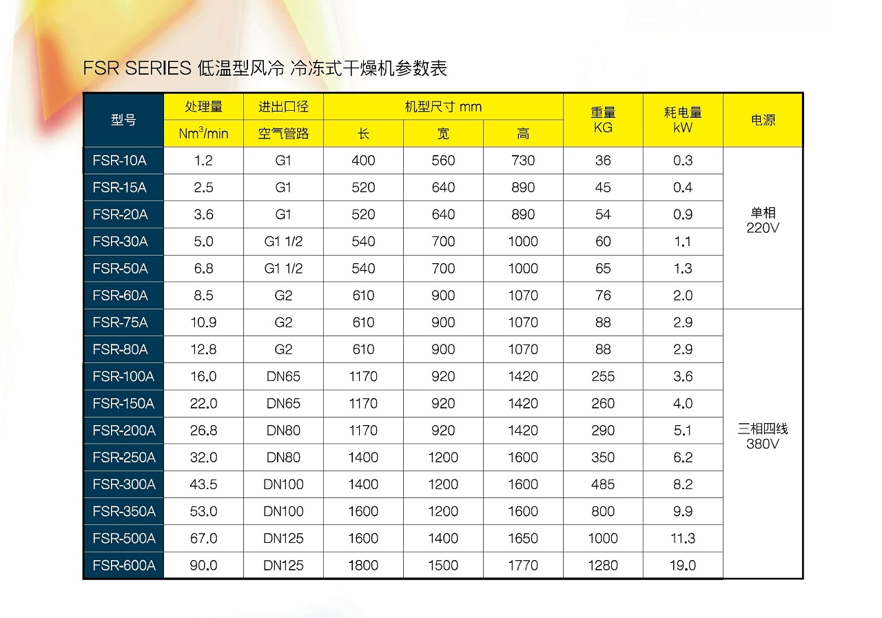
| Model | Nm"/min | Capacity | Inlet/Outlet Size | Air Piping | Dimensions mm | Weight | KG | Power Consumption | Power Supply |
|---|---|---|---|---|---|---|---|---|---|
| FSR-10A | 1.2 | G1 | 400 | 560 | 730 | 36 | 0.3 | ||
| FSR-15A | 2.5 | G1 | 520 | 640 | 890 | 45 | 0.4 | ||
| FSR-20A | 3.6 | G1 | 520 | 640 | 890 | 54 | 0.9 | Single Phase | |
| FSR-30A | 5.0 | G1 1/2 | 540 | 700 | 1000 | 60 | 1.1 | ||
| FSR-50A | 6.8 | G1 1/2 | 540 | 700 | 1000 | 65 | 1.3 | ||
| FSR-60A | 8.5 | G2 | 610 | 900 | 1070 | ||||
| FSR-75A | 10.9 | G2 | 610 | 006 | 1070 | 88 | 2.9 | ||
| FSR-80A | 12.8 | G2 | 610 | 006 | 1070 | 88 | 2.9 | ||
| FSR-100A | 16.0 | DN65 | 1170 | 920 | 1420 | 255 | 3.6 | ||
| FSR-150A | 22.0 | DN65 | 1170 | 920 | 1420 | 260 | 4.0 | ||
| FSR-200A | 26.8 | DN80 | 1170 | 920 | 1420 | 290 | 5.1 | Three Phase, Four Wire | |
| FSR-250A | 32.0 | DN80 | 1400 | 1200 | 1600 | 350 | 6.2 | ||
| FSR-300A | 43.5 | DN100 | 1400 | 1200 | 1600 | 485 | 8.2 | ||
| FSR-350A | 53.0 | DN100 | 1600 | 1200 | 1600 | 800 | 9.9 | ||
| FSR-500A | 67.0 | DN125 | 1600 | 1400 | 1650 | 1000 | 11.3 | ||
| FSR-600A | 90.0 | DN125 | 1800 | 1500 | 1770 | 1280 | 19.0 |
Official specification charts for this product — click to enlarge
Give us your working pressure, air demand and site conditions, and we will confirm the model and configuration